The golf ball and the design of a sleek business jet have much in common. Lift, drag, weight and gravity. These factors and more are part of the aerodynamics both the ball and the jet have in common. Why do golf balls have dimples?
Discovery of the Dimple!
Some 300 or more years ago, someone observed that an older, used ball with a roughened surface performed better than a new, smooth one—hence the start of why this is. As ball construction evolved they looked closer at this and progressed from a stitched pouch of skin stuffed with feathers to a natural rubber (gutta percha) ball. Introduced about 150 years ago, a roughened surface was recognized as an integral part of the design—just because it worked better at this point, no real science was applied.
The 1740s come along and Golf changed.
Newton recognized that transverse forces existed when spinning balls flew through the air. Magnus explained these forces in the 1740s, and their effect bears his name.
During the 1890s a professor at Edinburgh University was the first to study and describe his basic understanding of the aerodynamic principles of a golf ball. Professor Guthrie Tait was the first to apply science to flight of the ball.
He also was confirmed that the rough surface, in combination with backspin (underspin), created lift (known today as Magnus force). This allowed the ball to travel farther than a smooth ball launched at the same speed and launch angle without spin.
Today the size, shape, depth of these and dimple count all affect trajectory. Ball designs continue to evolve today. The common law of physics is governing how far the ball travels. The designs and modifications are at the limits of the equipment. Today’s manufactures are seeing much smaller gains in technology and ball flight in general.
What’s the science behind Dimples?
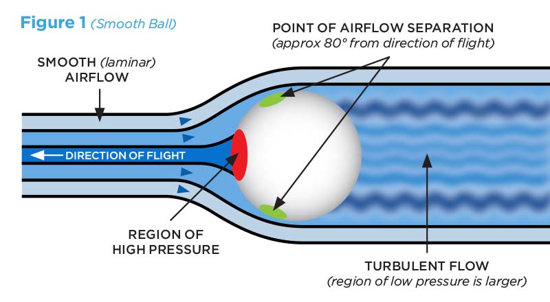
A smooth spin, as Figure 1 shows below for a smooth ball, results in a “separation” of the airflow from the ball, and the creation of a region of low pressure, turbulent airflow—a wake—behind it. This is similar to what happens over the top of a wing when it stalls. The difference in pressure between the front and back (or base) of the ball results in a resistive force, known as pressure, or base drag. Drag from lift also has a negative influence on the flight, known as induced drag. If the ball is cut, the cut may have parasitic drag effects on the ball. Using a clean undamaged ball will result in the “cleanest” flight, giving the golfer the maximum efficiently the ball can create.

Turbulent wake:
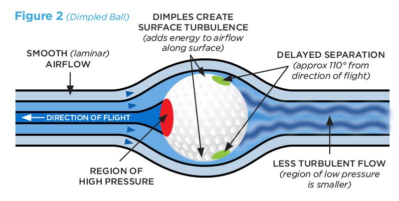
The dimples on a golf ball help by creating a small amount of turbulence in the air close to the surface of the ball.
Again neglecting the effects of spin, as Figure 2 illustrates, this turbulence actually helps “energize” the otherwise smooth (or laminar) layer of air closest to the surface of the ball. The added energy enables the air to make its way farther around to the backside of the ball against the increasing pressure. As a result, the point on the ball at which the airflow “separates” from it is pushed farther back. This reduces the size of the turbulent wake behind the ball and increases the overall pressure on its base.
The result is a reduction in the difference in pressure between the front and back of the ball, and therefore, a reduction in its base drag. There is some price to pay for this in the form of increased friction drag on the surface of the ball because of the turbulence. But the overall result for a golf ball is lower total drag and longer flight distance. The tradeoff works in favor of the golfer.

Falcons are widely recognized as the cleanest most aerodynamically “clean” business jet.
Golf ball manufactures strive to make the aerodynamics of the ball just a bit better every year. We will take an in-depth look at the factors that make a golf ball fly. First we should have some background on the cleanest plane in the sky, the all-computer designed Falcon. The aerodynamic shaping of today’s Falcons includes area ruling, wing and tail aerodynamic fairings and what is called smoothing or smooth laminar flow. Surprisingly the clean lines of the Falcon that make the drag very low are the same aeromechanics of drag that dictate how well and how far a golf ball will fly. Both the Falcon and the ball have what is called “Base Drag” (sometimes called boattail drag). Base drag is the most significant effect the golf ball need to over come in flight.
Similarly, as airflows around a Falcon towards the aft end of the fuselage and the static air pressure increases, the potential for significant base drag also exists. On some competing business jets there is a very abrupt, or “blunt”, closing of the fuselage, which further increases, the potential for base drag. As on a golf ball, tripping the otherwise smooth airflow along the fuselage into a turbulent state by using dimples or other similar methods could help delay separation of the air at the base and reduce base drag.
But in an aircraft, and particularly on a Falcon — for which such design approaches to airflow tampering are strictly taboo — this is not an acceptable solution, as the resulting friction drag would be very high. Instead, aircraft designs incorporate fuselage taper, and in the case of Falcons, aerodynamic shaping, also called “area ruling.” Designed correctly, this combination of shaping and taper minimizes the rate at which the static air pressure increases, enabling the airflow to more easily follow the contour of the aft fuselage and coalesce gradually back together as the aircraft passes through. The goal is to eliminate separation of the airflow from the aircraft without having to resort to creating wasteful turbulence on its surface.
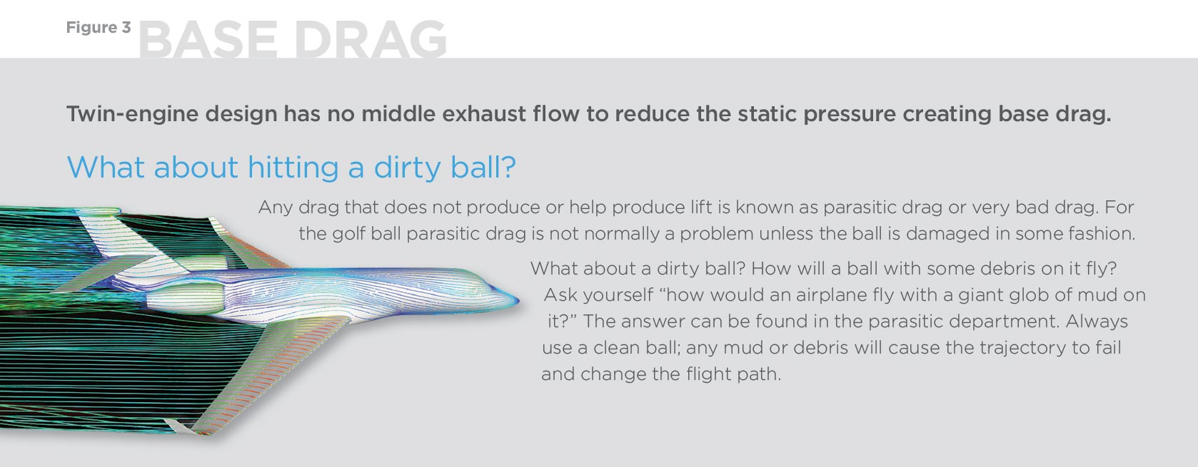
As with a golf ball, physics dictates the limitations on how quickly the air can coalesce as the aircraft passes through it (and how quickly the air pressure near the base of the aircraft can be allowed to increase). This places limitations on how severe the fuselage taper can be. A general rule of thumb for a conventional high subsonic aircraft is to limit the slope of the taper to 12 degrees from the free stream airflow direction (see Figure 3). On the other hand, the more gradual the taper, the longer the fuselage may become, leading to increased “wetted area.” Thus, too gradual a taper can make the fuselage longer than necessary, adding structural weight and increasing overall skin friction drag.
All modern business jets are designed within these parameters, some more effectively than others. For example, the Falcon 2000’s aft fuselage contours were created through extensive computer-aided design and analysis and its drag profile is highly optimized.
But how does a trijet Falcon’s configuration help? In a trijet Falcon, the exhaust of the center engine acts to fill in the base of the aircraft with a region of pressurized air, as a natural consequence of its design configuration. The static pressure of the air in the exhaust is nearly the same as the surrounding air. This inhibits the air flowing along the aft fuselage from “spilling into” the base region and separating. In addition, since the engine exhaust nozzle’s size precludes the requirement for the aft fuselage to come to a point, the aft fuselage can be designed with a more gradual taper. So, the air flowing around it encounters a more gradual static pressure increase and can coalesce more easily without separating. Combining this effect with the correct aerodynamic shaping results in a synergy of design wherein base drag is eliminated and friction drag is optimized. Incidentally, many high performance fighter aircraft, including Dassault’s Mirage and Rafale series, incorporate a similar design approach, where the engines exhaust flows into the base region of the aircraft.
Things have changed. The USGA has perfected the “Indoor Test Range” (ITR), which supersedes wind tunnel testing.
The aerodynamic properties of a ball are now tested at the USGA Indoor Testing Range (ITR), a 70-foot-long open area with a series of stations along its length. At each station, the exact ball position and speed are measured as it passes by. This method of firing a spinning ball through a still body of air has proven to produce far more accurate and reliable data than trying to support a spinning ball in a laminar stream of air in a wind tunnel.
From the information collected in the ITR, the coefficients of lift and drag for a number of different speeds and spin rates are calculated and combined for use in a simulation to describe the complete trajectory of any golf ball test.
To further match the optimum launch conditions with the golfer, club design is changing in order to reduce the spin rate, launch the ball higher and launch it with more speed. The spring-like effect has been a major advance in club design. The new advances in clubs will also have impact on how the trajectory is affected in the future. Club technology and the spin rate created by the technology is making the advances.

Take Off: Flight Path Trajectory
As soon as a golf ball is launched off a driver, it starts its trajectory with lift forces overcoming the weight and gravity of the ball. Base drag and induced drag from the lift are now in play.
As the ball accelerates, it is able to cover a distance of approximately 265 yards in the air and then bounce and roll on to about 290 yards in total.
A smooth ball with otherwise identical physical properties, launched in the same manner, will only travel about 140 yards. The effects of a dirty ball will also have adverse effects on the launch, even though the debris or mud will soon depart because of the forces the initial launch is greatly affected.
The reason for this is that when the golf ball passes through the air, the dimples help produce laminar flow because the roughened surface creates a layer of turbulence at the surface of the ball.
As it spins, the laminar flow around the ball creates a profile of disturbed air similar to an airfoil. This then works the same way as a wing causing a low and a high pressure. The result is the ball is being sucked up into the air, creating the lift force which allows the ball to stay in flight for longer periods of time than a smooth ball.
It is unfortunate that these same forces, which create lift, also create a hook and slice (an undesirable deviation left or right of the target) when the axis of spin is tilted to the left or right. This is caused from the lift vector being moved form 90 degrees from the club head to some other angle changing the lift vector. The USGA has testing standards for all golf equipment, and the golf ball is the most tested of all.
How does a crosswind, tailwind or headwind affect trajectory and rollout? We will address these in our next look at Golf Ball Aerodynamics. The headwind is desirable when hitting onto the green! A tailwind is desirable from the tee box on a Par 4 or 5.

